![]() Automotive
Engines
Automotive
Engines
What Can We Offer?
Magnesense originally set out to improve the automotive-scale electric valve actuator in several areas. All the items in our patent portfolio are applicable to the automotive scale, while some of them apply to small engines as well. Our major areas of innovation are:
· Sensorless Position and Velocity (patented)
o
“continuous” (currently operating at 10,000 position
samples/second)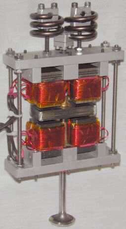
o based on electric current measurements at the controller
o gives position, velocity, and flux linkage – the things a controller “needs to know” to control magnetic force and mechanical motion
o adapts automatically to changing actuator characteristics (particularly changing resistance of windings as they heat up)
o the technology is tested and “real”
· Theory and Modeling (discussion)
o technical papers
· State Space Control (patented)
o a demonstrated, effective feed-forward control technique
o utilizes specific knowledge of the characteristics of the chosen actuator
o tracks and adapts to deviations from baseline actuator characteristics
o can provide an engine controller with data about cylinder pressure (at valve-opening time) and gas flow past a valve (during valve transit or partial lift), helping the controller to fine-tune engine operation (including potentially for HCCI operation)
· Single Winding Solenoid (patented)
o shows how to cut the drive electronics in half
o almost the same actuator efficiency for much lower cost
o applicable to existing solenoid actuator designs (just re-connect the windings)
· A spring that fits the needs of electric valve actuation (patented)
o fits a low-profile rectangular envelope
o inexpensive (ends of the single spring wire are simply cut, not ground flat)
o push-pull operation handles most of the spring work in a single spring
o minimizes moving mass (thus improving actuator speed)
o this spring has been developed from theory, fabricated, and tested
o we have the design tools to adapt this spring design for any customer
· “Flat Lamination” armature design (patented)
o an outstanding tradeoff between good electromagnetics and mechanical strength
· Fast, fixed-point DSP control
o Magnesense has mastered the difficult challenge of scaling dynamic controller software to operate in fixed point and integer arithmetic on a DSP, thus achieving much more performance-per-dollar than a comparable floating point processor
o Magnesense can help a customer achieve the same goal
· We understand magnetics and controls. We can help our customer.
o we can tailor the magnetic force curve of a solenoid and add passive windings that damp the landing while not interfering with active actuation windings (patented)
o we have written and used 3D magnetic FEA software, so we know how it works
Sensorless Position Measurement
Bergstrom’s approach, as described and claimed in his patent System for Control of an Electromagnetic Actuator, was part of the original motivation to found Magnesense. Our patent summaries section provides a good description, as reviewed briefly here. The crux of the invention is indirect measurement of armature position based on measurement of the solenoid winding current, occasional voltage measurements (to track the relatively slow fluctuations of the power supply voltage) and computations that determine the average inductive component of voltage driving the solenoid winding. The winding flux linkage is determined by time-integration of this inductive voltage, with drift corrections applied when the valve is open or closed. Armature position is computed at frequent short intervals along a trajectory (presently at a 10 KHz sampling and update rate), based on the changing ratio of current/flux-linkage. Magnetic force is implicit in the position and flux linkage data. Thus, the system has robust information for control. No sensors are required in the actuator, and extra sensor wiring to the actuator is avoided.
Actual implementation of this method has proved time consuming, requiring good models and a thorough grasp of the entire electromagnetic process. Having mastered the subtleties of our own system and achieved excellent sensorless position measurements, the technique can be adapted to operate the actuators of other companies, simplifying them and reducing costs.
Theory and Modeling (overview)
Much of our effort has gone into the area of sensorless control using an inexpensive Digital Signal Processor (DSP). This work spans from advanced theory to detailed real-time control software implementation in fixed-point and integer arithmetic. Here is a very brief outline of that spectrum.
At the theory end, our thinking has oriented to the thinking described in the twin papers:
Magnetic Analysis by a Flux-Centered Approach
Part 1: Choosing Flux Linkage As An Independent Variable
Part 2: Basic Equations for Solenoids with Ideal Ferromagnetic Conductor
As we have refined our controller models in light of empirical data, we have begun to incorporate corrections for the effects of non-ideal magnetic properties of iron (relating the field strength "B" to the magnetomotive force "H"), incorporating information described in a third paper:
Building on theory, we have developed dynamic simulations of solenoid operation, then of system operation including both the simulated solenoid and the sampled data system controller. Early simulations were in Spice (an electronic circuit oriented simulation language), then in Scilab/Scicos (similar to Matlab/Simulink), and recently largely in spreadsheets. We have found Excel to be quite capable of handling open-loop dynamic simulations on one page, then passing control system parameters and state-space tables to a closed-loop controller simulation page within the same spreadsheet. When the simulated controller works well, the state space tables are cut and pasted into our DSP control software, where with minor adjustment we are able to replicate, in hardware, the kind of performance that was predicted by the spreadsheets. This process forces us to reconcile theory with practice until the models are accurate and reliable, matching real hardware over a range of operating conditions. Spreadsheets provide a highly transportable medium of communication, as virtually any engineer can open one of our Excel spreadsheets, be instructed to go to the cell of some design parameter of interest, vary it, and watch graphs of how the system response changes.
While evaluating our system (in this case, an actuator adapted for small engines but obeying principles applicable to larger and smaller scales), an independent position sensor tells us how well our sensorless theory is working. The sensor data remains separate from control operation, being only for display and for our understanding.
Our sensorless position measurement and control technology is challenging to implement. In a system that incorporates a separate sensor, that sensor is separately developed and comes calibrated, providing data that do not depend on a deep understanding of dynamic solenoid operation. To calculate position using measured current and a time-integration of flux linkage, everything has to be right. Applied voltage has to be separated into components of inductive voltage and resistive voltage, where a small error in the coil resistance parameter throws the computation off. Likewise, the flux linkage integration process must be initialized properly under difficult circumstances, for example, when a solenoid armature has been latched long enough for the flux linkage to drift, so that the releasing flux is not accurately known. The software is designed to self-correct for such errors, for example by relating the magnetic properties of the two sides of a solenoid and determining consistent parameters.
Is all this effort worth it? Absolutely. There is the obvious issue of cost saving. There is the issue of eliminating sensor wiring, which would have to go into the harsh environment under a valve cover. There is the issue of component and wiring reliability. As important as these practical concerns, however, is that the controller always knows, accurately, the total electromagnetic state of both sides of the solenoid actuator, corrected for fluctuations in performance parameters over time. Thus, the system knows not only position and velocity, but the magnetic force that is being generated. The feedback algorithm, in making iterative corrections to fine-tune soft landings, comes to “recognize” the effects of external perturbations: actuator friction, gas forces, etc. Once the software is working and the system is understood, it is understood deeply, at a level than can lead to future improvements in fine tuning of engine operation – even potentially into the tricky area of HCCI operation. Electric valves become sophisticated tools for both control and sensing.
Our “State Space Control of Solenoids” patent, again described under the patent summaries, incorporates the knowledge and experience of the previous two sections. There are two main features to this control approach:
· control of flux linkage as a function of position and velocity; and
· pre-defined trajectory information in the (position, velocity, flux-linkage) space, adapted to the specific characteristics of the solenoid to be controlled and defining, from any point in this state space, what the next controller output voltage should be.
The time integration of inductive voltage to yield flux linkage, and the closely related process of controlling flux linkage, come out of item #2 of this narrative, sensorless position measurement. The pre-defined trajectory information comes out of the simulations of item #1. This information effectively spans a band of state-space trajectory paths surrounding a central “ideal” trajectory. Implementation of this technique relies on item #4, as now described.
Valve control solenoids that latch in both valve-open and valve-closed positions have required two windings and two sets of drive circuitry. Sagem has patented a solenoid using just one coil, but the dual latching function is achieved by a very inefficient routing of magnetic flux, making the solenoid considerably larger and much less efficient. Our system starts with a conventional yoke and winding topology but then wires the two windings is series and connects the series-pair to a single drive circuit. This approach may sound inefficient, but in the final analysis it is almost as efficient as the old approach and considerably cheaper.
Making this approach work requires that a double-acting solenoid be spring-biased off-center, so that it can be vibrated at resonance and latched after several vibration cycles. The asymmetry is chosen so that the springs help the actuator move in its more difficult direction, e.g. against the pressure of combustion products for pushing an exhaust valve open. Once the valve is latched, the series winding current is reduced to induced armature release, then brought back up to pull in and latch on the opposite side. Very little magnetic force bridges across the middle between the two yokes to cause force cancellation, so the two sides, driven with equal currents, only interfere minimally. The inductance of the yoke farther from the armature is low, and the magnetic fields there are weak, so that magnetic losses on the “unused” side are minimal. There is an efficiency loss due to the extra series winding resistance of the unused coil, which causes the latching power consumption to rise. In a practical design, however, the DC resistance of a winding is less that 0.2 ohms, typically of similar magnitude to the resistance of the drive circuitry. Dynamic losses with the series-wound yokes are hardly larger than for individually-driven yokes. In the final analysis, the “single winding” design consumes little more power than a conventional design, and the cost saving is considerable.
A Spring for Valve Control in Engines
Our first engine valve solenoid became a platform for trying out a new development: a spring that would fit the geometry of a cylinder valve solenoid. The approach with other solenoids, then and to this day, relies on two large opposing compression springs, where the lower spring is often set into the engine block. Each of these springs is quite a bit larger than an ordinary valve return spring, as needed to achieve the high centering force required to move a valve quickly between its full-open and full-closed positions. We figured that if the valve return spring could go back to the conventional size for cam engines, then the remaining restoration force could come from a compact push-pull spring fitting above the solenoid. The compression force at the valve lash adjustment gap would then be considerably lower, reducing the discontinuity in actuator force to move the solenoid from the valve-closed point to the armature gap-closed point. This would smooth the step in the soft landing process and lead to a gentler overall dynamic.
By designing a spring capable of both compression and tension, we could operate the spring metal almost symmetrically about a neutral stress, allowing for considerably more energy storage per unit of spring mass. This mass reduction would lead to a physically smaller spring as well as a faster actuator. We settled on side-by-side helices, joined across the middle, as a way to fit the flat rectangular envelope needed to stack valve actuators up side-by-side at the spacing needed in a multi-cylinder engine. The side-by-side coils squeeze the needed spring material into a small vertical space. We developed a spring design spreadsheet that, for reasonable geometries, provided all the stress and fatigue information of a full 3-D FEA analysis – the bent spring wire was treated as a line in space rather than a solid, and empirical formulas accounted for the finite wire radius in computing worst-case local stresses. The spring outline was graphed on the spreadsheet, along with the maximum geometric extents of the spring, worst-case local stress for a maximum excursion, etc. Three columns of spring path coordinates then dropped into a solid modeling program to provide a complete image and drawings for the spring fabricator. Thus, we developed a powerful and easy-to-use design tool with which to design any spring of our type of geometry to custom specification.
We interested Peterson Spring in the project, and they agreed to bend some prototype springs for testing. They reported that a machine could probably be built to bend springs of this type so that, in volume, the springs would be significantly cheaper than compression springs requiring their ends to be ground flat. The clamping hardware, made from extruded aluminum pieces, would be inexpensive and add little moving mass.
The big challenge was to capture the spring ends and middle in a way that would allow reversing push-pull forces without developing any slop and without chafing the spring metal at the clamp. We developed a clamp design in which a hard rubber sleeve would surround the spring wire and be clamped in high compression. Rubber gets torn apart by tension or an alternation of tension and compression, but our studies of elastomer dynamics (see Seale’s U.S. Patent 6,631,647, System and Method for Quantifying Material Properties) indicated that if the rubber were kept in compression at all times, and if the force transferred from the clamp to the wire were transmitted mostly as differences in positive pressure rather than by shear forces, then the rubber would last indefinitely.
The solid model image shown below
and the adapted patent figure illustrate the concept. The curved lines (767) crossing the rubber sleeve (633)
indicate how straight radial lines across the sleeve become distorted by
shear forces when the large spring wire (410) in the middle is pushed down
(force arrow 763). The moderate shear in the rubber
gives rise to a large difference in pressure from top to bottom, opposing
the large downward force of the wire almost entirely by high pressure below
and a lower positive pressure above. The squeezing
force of the clamp (arrows 751, 762, 764 and 765) assures that the rubber
is always in compression, which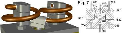 it withstands without damage. The pressure tapers
off to zero at the ends of the sleeve, where all the stresses are moderate. Half the patent specification and important allowed claims
are devoted to the clamping method. The economy
of this design is that the spring ends do not require grinding, as with
compression springs. Thus, this compact spring is
expected to fit in an available rectangular space, add less moving mass than
opposing compression springs handling the same forces and motions, last indefinitely,
and cost less, even counting the cost of the clamps.
it withstands without damage. The pressure tapers
off to zero at the ends of the sleeve, where all the stresses are moderate. Half the patent specification and important allowed claims
are devoted to the clamping method. The economy
of this design is that the spring ends do not require grinding, as with
compression springs. Thus, this compact spring is
expected to fit in an available rectangular space, add less moving mass than
opposing compression springs handling the same forces and motions, last indefinitely,
and cost less, even counting the cost of the clamps.
Another design innovation tested in our prototype was
the flat-lamination armature, illustrated schematically in the patent Figs.
3 and 4 below. Referring to the patent
Fig. 3,
the optimum configuration for minimized eddy currents would use
narrow 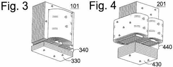 vertically-stacked “I-core” laminations for armature 330, putting these
laminations in the same plane as the “E-core” laminations above them. This stacking direction would lead to a very weak armature,
easily broken along the cleavage boundaries of the laminations. Pinning or welding of vertically stacked laminations would
open up eddy current conduction pathways, significantly reducing the advantage
of having laminations. Industry practice with valve
solenoids was to use a solid armature, accepting considerable eddy current
losses. We recognized that the eddy losses for the
horizontal stacking pattern of the Fig. 3 armature would be only slightly
worse than for the fragile vertical stacking pattern while lending much
greater strength. Patent claims to this effect were
allowed, while actual operation of the solenoid confirmed our expectation
of acceptable eddy current losses.
vertically-stacked “I-core” laminations for armature 330, putting these
laminations in the same plane as the “E-core” laminations above them. This stacking direction would lead to a very weak armature,
easily broken along the cleavage boundaries of the laminations. Pinning or welding of vertically stacked laminations would
open up eddy current conduction pathways, significantly reducing the advantage
of having laminations. Industry practice with valve
solenoids was to use a solid armature, accepting considerable eddy current
losses. We recognized that the eddy losses for the
horizontal stacking pattern of the Fig. 3 armature would be only slightly
worse than for the fragile vertical stacking pattern while lending much
greater strength. Patent claims to this effect were
allowed, while actual operation of the solenoid confirmed our expectation
of acceptable eddy current losses.
The above methods and theories are of little use without
fast digital processing to implement real-time feedback control. We chose a Digital Signal Processor (DSP) approach (Motorola
56800 family), rather than a general purpose microprocessor, as best adapted
to the task. We also took on the challenges of working
with fixed-decimal and integer arithmetic, rather than floating point, as
an economic necessity. We found a DSP family already
tailored to motor control applications and developed appropriate interface
circuitry. The ensuing process of hardware and software
implementation has been laborious and time-consuming, and the results outstanding.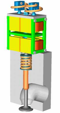
Refined Automotive Valve Solenoid
Based on our experience with the experimental prototype, we designed a much more compact valve solenoid having lower moving mass, higher speed, and handling the same gas forces acting on the valve. The design again incorporated a flat-lamination armature. The design is shown in a color-coded solid model on the right.
Conclusion
Magnesense has developed an array of related technologies to improve the economy and performance of electric valve actuation solenoids, including the electronics, the digital processing hardware, and the software that go with that task. We have been too small a company to undertake complete valve systems operating in an automotive engine. Much of our practical experience has been in developing an actuation system meeting the economic imperatives of the small engine market. That work has carried us into unexplored design territory, yielding results that are applicable on both the small engine and automotive engine scales. Some of the cost-saving ideas developed for small engines carry back to the automotive-scale context.
To realize the practical value of our technology, we need to collaborate with an industry partner, understand that partner’s needs, and help that partner in a broader context than we can begin to handle independently. We understand the broad context of electric engine valve design, from theory to practice, though we are not experts in the area of combustion engineering. We need collaborators. We communicate well. Much of our technology can improve the performance of existing or emerging designs without redesign from the ground up. We are dedicated to assisting in turning this promising area of technology research into a practical and economic reality, to make fundamental improvements in the internal combustion engine.
Magnesense LLC Gorham,ME (207) 839-8637
©2009 Joseph Seale